Hall Sensor
Principle
Hall sensor is a magnetic sensor designed based on the principle of Hall effect. According to the Hall effect principle, when a current is applied in a conductor along a certain direction and a magnetic field is applied vertically in this current direction, a potential difference proportional to the strength of the current and the magnetic field will be generated on both sides of the conductor. This phenomenon can be used to detect the presence of an external magnetic field, that is, when the sensor is close to a magnetic object, a specific Hall voltage will be generated, and the corresponding electrical signal will be output to indicate the presence of the magnetic field.
Specifications
Item |
Description |
|---|---|
Name |
Hall Sensor |
Code |
B0020009 |
Dimensions |
28 x 24 x 12 mm |
Voltage |
5V - DC |
Data Type |
Analog Signal |
Data Range |
0 or 1 |
Ports |
Grove |
Usage
|
||
|---|---|---|
|
|
|
Side View |
Front View |
Side View |
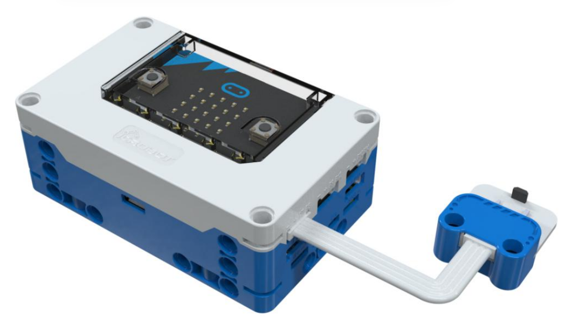
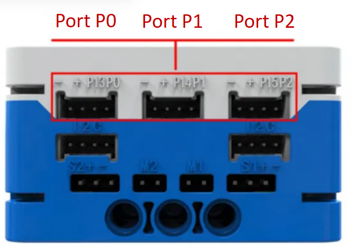
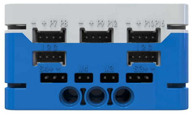
The Hall sensor can be connected to the P0, P1, P2, P8, P12, or P16 ports on the micro: bit hub. By coding, its output value can be read. When a magnet is detected nearby, the Hall sensor outputs a low logic level (0). In the absence of a magnet, it outputs a high logic level (1).
If the magnet is not detected, indicating the opposite polarity, the detection magnet can be flipped out.
Modular Coding
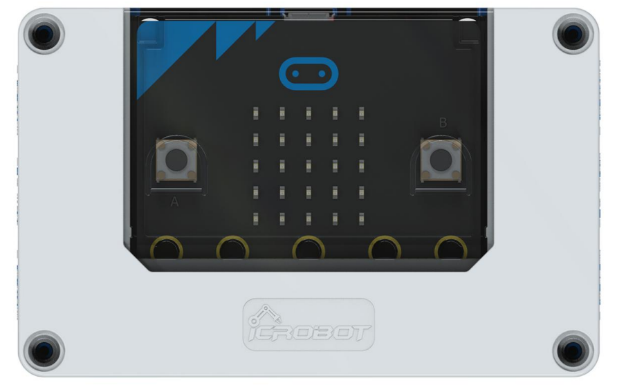
In the MakeCode coding software, the sensor’s signal value from the P0 port can be read using the Microbit extension. The data can then be visualized on the micro: bit’s LED matrix.