Joystick Module
Introduction
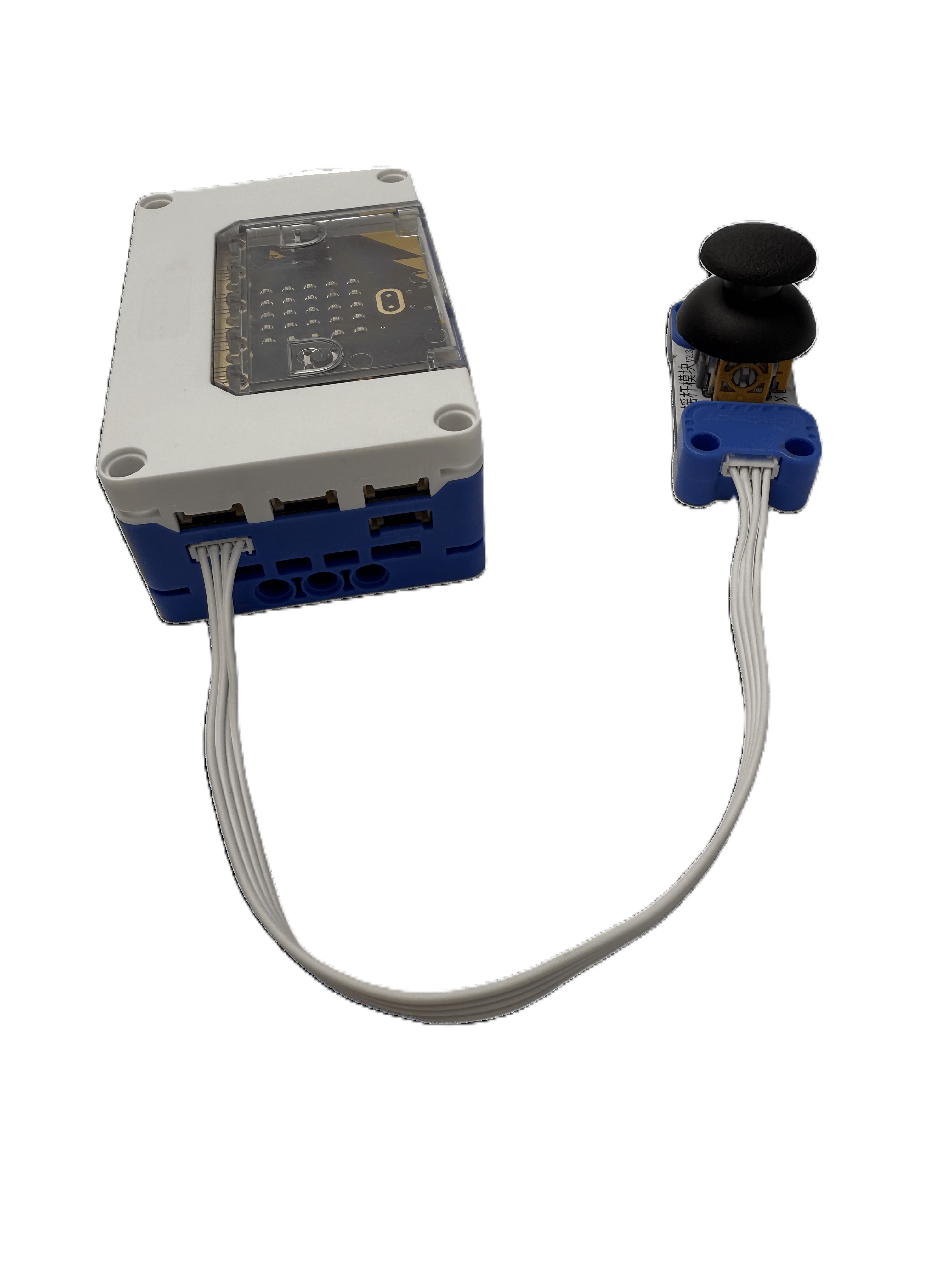
The joystick module is a commonly used electronic input device, primarily designed for directional and amplitude control. It consists of a movable joystick and an internal potentiometer. When the joystick is tilted, its position changes the resistance value of the potentiometer.
Specifications
Item |
Description |
|---|---|
Name |
Joystick Module |
Code |
B0020029 |
Dimensions |
51×24×34 mm |
Voltage |
5V-DC |
Control Signal |
I²C |
X / Y Axis Detection Range |
-100~100 |
Ports |
Grove |
Usage
|
|
|
|---|---|---|
Side View |
Front View |
Side View |
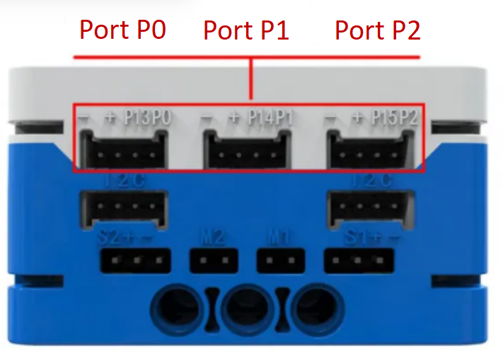
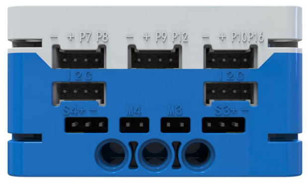
The joystick module can be connected to the I²C interface of the micro: bit hub. In the coding environment, the position of the joystick can be read and utilized.
If the joystick module exhibits accuracy deviations, calibration can be performed using tweezers: Short-circuit the calibration pads with tweezers. The indicator light will start flashing, indicating calibration mode. Perform a full 360° rotation of the joystick. After completing the rotation, remove the tweezers. When the indicator light turns solid, calibration is successful.
Modular Coding
Using the MakeCode coding software, the Microbit extension allows:
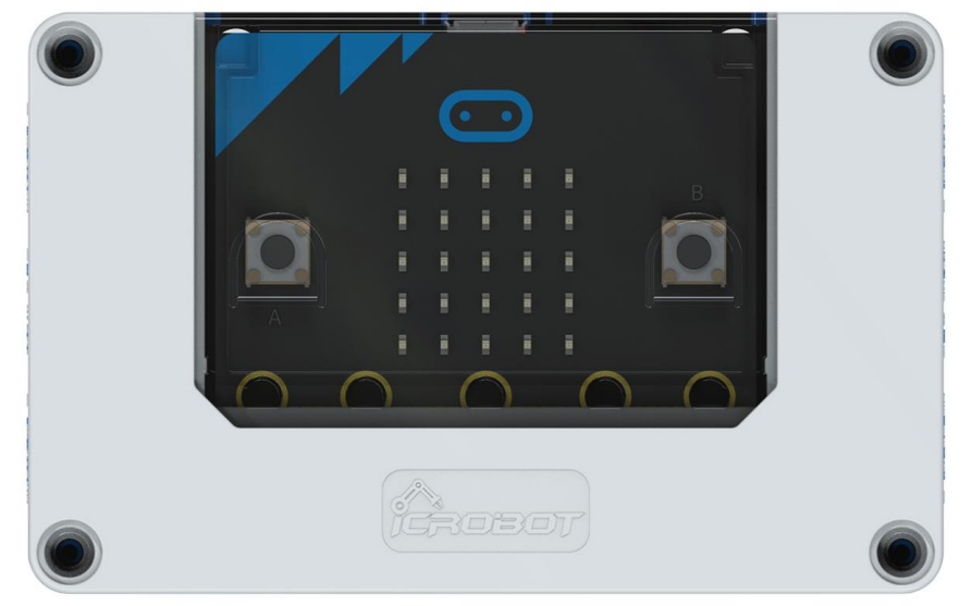
Reading directional signals from the joystick module through the I²C port and displaying them on the micro: bit LED matrix.
Reading positional values from the joystick module through the I²C port and writing them to the serial port.