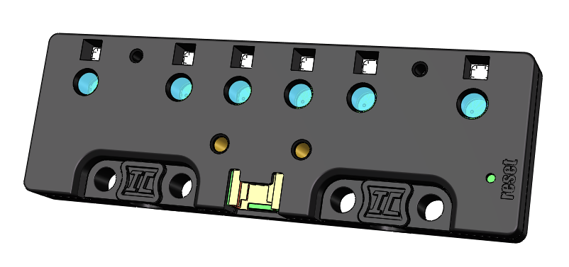
Six-Way Color & Grayscale Sensor
Principle
Color Detection Principle
Each pair of color sensors combines the functions of a photosensitive sensor and an RGB LED, forming a powerful detection unit. In the real world, when we perceive an object as red, it usually indicates that the object reflects more red light and absorbs other colors more effectively. Based on this principle, when red supplemental lighting is used, the higher the object’s red color, the stronger its reflection of red light, and the higher the reading of the photosensitive sensor. This mechanism enables us to quantify the object’s “red index.”
Similarly, by adjusting the color of the supplementary light to cycle between red, green, and blue, and simultaneously recording the readings of the light sensor at each moment, we can accurately calculate the object’s “green index” and “blue index,” and then infer the overall color of the detected object.
Environmental Interference and Detection Error Analysis
In the physical world, environmental interference and detection errors are common issues. The color sensor’s ability to detect the color of an object depends on the intensity of light reflected from the object under the supplemental lighting. However, ambient light can also be captured by the light sensor, introducing errors. Even under the same environmental conditions, two dual-color sensors may produce different readings when detecting the same object due to individual variations.
To address these issues, we have carefully designed the sensor casing to isolate the detected object from the sensor, effectively shielding it from ambient light interference. Furthermore, we have developed advanced algorithms that record sensor readings with the supplemental lighting on and off, and calculate the difference between the two. By assuming ambient light intensity remains unchanged during this brief period, this method minimizes errors.
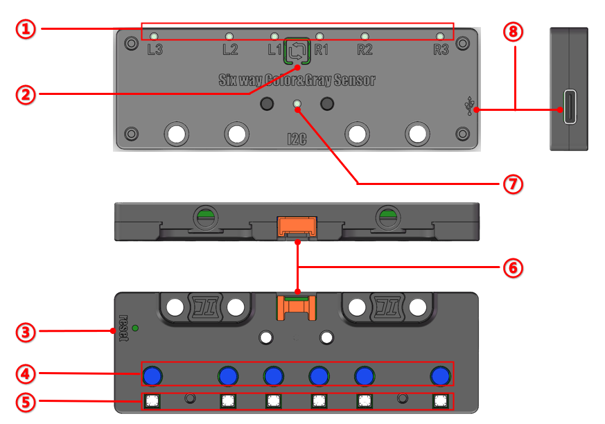
Structure
No. |
Item |
Description |
|---|---|---|
① |
Indicator Light |
Lights up when the corresponding probe detects a “black line.” |
② |
Learning Button |
Press once to enter learning mode; long press to change device address. |
③ |
Reset Button |
Used to reset the sensor. |
④ |
Sensor Probes |
The six probes of the Six-Way Color and Grayscale Sensor. |
⑤ |
Supplementary Light |
Supplementary light corresponding to each probe. |
⑥ |
Interface |
HY2.0-4P port for power supply and signal transmission. |
⑦ |
Address Indicator |
Indicates the device address; different colors represent different addresses. |
⑧ |
Type-C Interface |
For power supply and firmware updates. |
Specification
Item |
Description |
|---|---|
Name |
Six-Way Color & Grayscale Sensor |
Code |
B0200011 |
Voltage |
5V-DC |
Communication Method |
IIC |
Detection Range (Grayscale) |
Analog output (0~255) / Digital output (0 or 1) |
Detection Range (Color) |
Red, Yellow, Green, Blue, Purple |
Sensor Count |
6 Channels |
Ports |
Grove |
Dimensions |
96 x 32 (mm) |
The Six-Way Color and Grayscale Sensor uses IIC communication. Below is the IIC communication address and corresponding indicator light table:
I²C Address |
Indicator Light Color |
|---|---|
0x70 (default) |
None |
0x71 |
White |
0x72 |
Cyan |
0x73 |
Magenta |
0x74 |
Blue |
When using I²C communication, ensure that all sensor addresses are unique to avoid communication errors.
Usage
Connection Diagram
|
|
|
|---|---|---|
Side View |
Front View |
Side View |
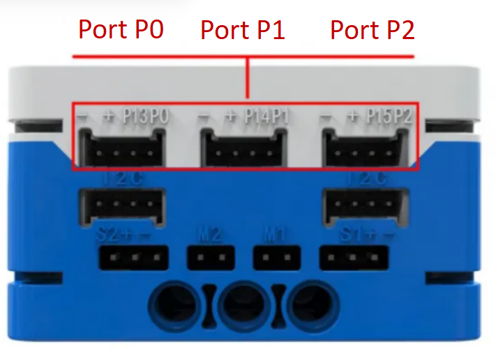
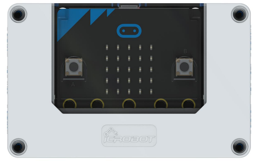
The Six-Way Color and Grayscale Sensor uses IIC communication and can be connected to any I²C interface on the micro:bit Intelligent Hub.
Analog and Digital Output
The sensor can output data as either an analog signal (range 0 ~ 255) or a digital signal (0 or 1) through any port.
For accurate interpretation of the analog output, environmental light values should be learned in advance. If the sensor is used in a different lighting condition than it was trained in, the readings may vary significantly. It is recommended to perform environment adaptation learning before actual use.
The digital output function is used to distinguish between a black line and the background. The threshold for determining the line or background depends on the learned values, so it is essential to perform environment-specific learning.
Modular Coding
Click here to access the Six-Way Color and Grayscale Sensor extension.
Address Selection
The sensor has one default I²C slave address and four selectable addresses, which are indicated by different LED colors. When only one sensor is in use, the default address 0 can be used. When multiple sensors are used, each should be assigned a unique address, and the corresponding group number should be selected in the programming interface.
Note: If more than one sensor is used and the same address is set, the control will be abnormal.
I²C Address Switching
To switch the device’s I²C address, long press the learning button and wait for the address indicator light to change color. Release the button when the desired address is reached.
The following table lists the correspondence between the I²C slave address of the device, the color of the sensor indicator and the group number in the program extension. Please pay attention to the comparison.
I²C Address |
Group Number |
Color |
|---|---|---|
0x70 (Default) |
0 (Default) |
Any |
0x71 |
1 |
White |
0x72 |
2 |
Cyan |
0x73 |
3 |
Magenta |
0x74 |
4 |
Blue |
Program Calibration
When the sensor is installed in a location where direct operation of the learning button is difficult, the sensor can be controlled through a calibration program block. By selecting an address number (0 ~ 4), the corresponding sensor can be instructed to enter learning mode. For the specific steps of the learning operation, please refer to the button learning function described in the previous section.
Serial Output
The serial output block allows users to read the analog values from all six probes of the sensor simultaneously, improving the efficiency and stability of data collection.
Note: The analog values read are essentially real-time feedback based on the learned results stored in memory, reflecting the current detection environment.
Digital Output Block
The color detection block features color recognition capabilities, allowing it to identify the color of a selected probe at a specified address and output a clear logical value (“Yes” or “No”). This module can accurately distinguish five colors: red, yellow, green, blue, and purple.
Line-Following Detection Block
This block accurately differentiates black lines from backgrounds and provides logical outputs (Yes or No) based on the learned environment. Note that the “black line” and “background” recognized by this module are based on learned environmental light conditions. The “black line” represents areas with lower light reflection intensity, while the “background” refers to areas with higher light reflection intensity within the learned detection area.
Analog Output Block
The analog output block converts the reading of a selected probe into an analog signal (0 ~ 255 range) for output.